A Deep Dive into Modelling System Behaviour and Dynamics
The Function-as-a-Seed OPM Principle
When developing a complex system, two crucial concepts that need clear definition are purpose and function. The purpose is the solution-agnostic goal that the developer aims to achieve, while the function refers to the “how” — the way a system is designed to organise itself to carry out specific actions in order that the purpose may be accomplished.
This distinction is integral to system modelling, particularly in Object Process Methodology. According to the Function-as-a-Seed OPM Principle, every system model begins with the definition, naming, and depiction of the system’s function, which serves as the top-level process. The purpose is then modelled as the desirable effect or outcome resulting from this function.
This approach highlights a key difference between OPM and Object-Oriented methodologies. In OO, processes, often referred to as methods or operations, are inherently tied to objects. However, in OPM, processes can exist independently. This independence allows for the modelling of a system’s purpose without confining it to a specific solution, making it possible to convey the system’s intent effectively and unambiguously.
The Two Types of Procedural Links
In the first part of this series, we examined how OPM’s four fundamental structural relations describe the persistent, structural aspect of a system. Now, in the second part, we’ll shift our focus to the dynamic, behavioural aspect, along with the system’s purpose and function, which are captured through procedural links in OPM.
If you missed the first article on OPM’s structural relationships, you can catch up here.
According to the Object Transformation by Process Principle in OPM, every process in a model must be linked to at least one object or its state in which the process transforms. This principle ensures that each process is clearly defined in terms of what it accomplishes within the model. Such transformations are represented using procedural transforming links.
However, understanding what a process does isn’t always enough, we often need to know who performs the process, what tools or equipment are used, or which subsystems are involved. This is where procedural enabling links come into play.
In this section, we’ll dive into the significance and practical applications of these two types of procedural links, examining how they help in accurately modelling the dynamic interactions and dependencies within a system.
Procedural Transforming Links
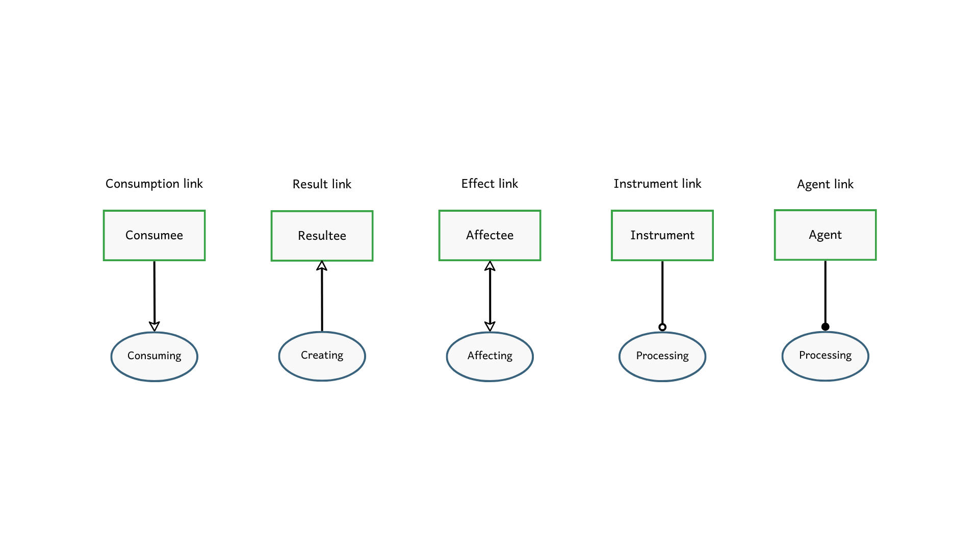
In OPM, transformation is defined as either 1) creation, 2) consumption, or 3) effect — a change in the state of an object. Each of these transformations is represented by a corresponding procedural transforming link.
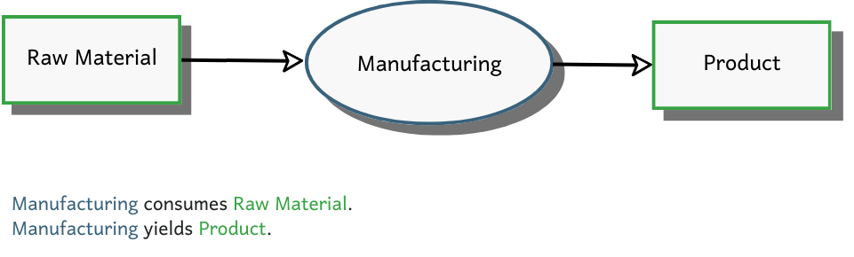
The consumption link is a unidirectional arrow that originates from the object being consumed and points to the process that consumes it. For instance, in a manufacturing process, the raw material is consumed, so the link would go from “Raw Material” to “Manufacturing”. On the other hand, the result link represents creation, with the arrow direction being the inverse of the consumption link. As “Manufacturing” consumes “Raw Material”, it produces a “Product”. Hence, the result link goes from “Manufacturing” towards “Product”. Together, these consumption and result links clearly illustrate which objects cease to exist and which new objects are created as a result of the transforming process.
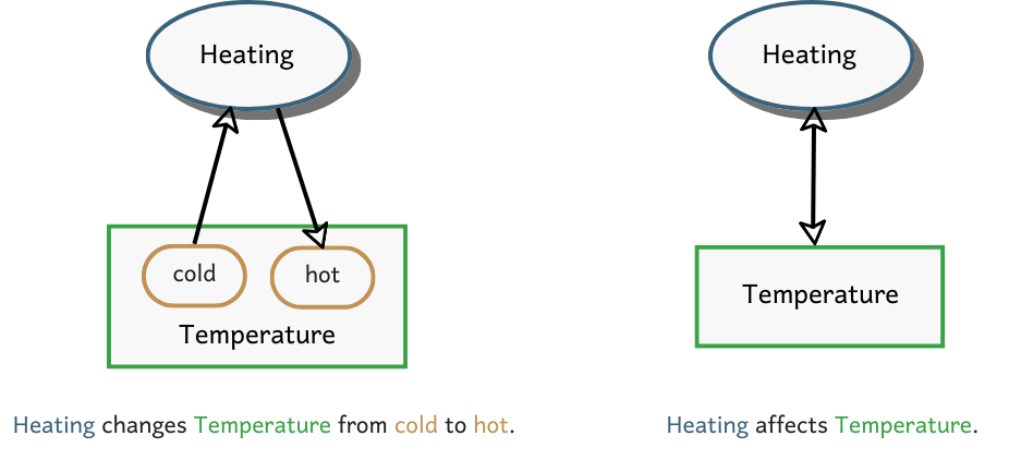
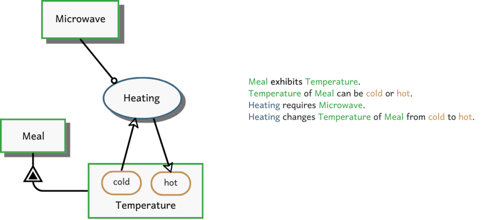
However, not all transformations involve such significant changes. More subtle transformations can be modelled using the in-out link pair. For example, consider the process of heating, which changes the temperature from cold to hot. This can be represented by an in-out link pair, where one arrow goes from the “cold” state of “Temperature” to the process “Heating”, and another arrow goes from “Heating” to the “hot” state. One way to think about it is that, “Heating” consumes “cold” and outputs “hot”. To simplify, this in-out link pair can be collapsed into a single bidirectional effect link, abstractly representing the fact that “Heating” affects “Temperature”.
Procedural Enabling Links
You might find yourself puzzled by the heating example above, wondering what is heating what, and how temperature comes into play. This is where procedural enabling links and the exhibition-characterization link, which we discussed in the previous article, become essential.
To clarify, the scenario I intended to illustrate involves a microwave heating up a meal. In this model, an instrument link connects the “Microwave” to the “Heating” process, indicating that the microwave is the system responsible for carrying out the heating function. The fact that “Temperature” is a property of “Meal” is captured through the exhibition-characterization link.
To complete the model, we can also specify a human operator is required by connecting “Person” to “Heating” using an agent link. Together with the procedural transforming links, these connections provide a clear understanding of the system’s dynamics and interactions.

In OPM, the instrument link is represented by a white circle, while the agent link is shown as a black circle. This distinction helps us clearly differentiate between the system or component and the human operators, effectively highlighting any potential human-in-the-loop involvement.
Operation and Control
While the procedural links discussed earlier lay the groundwork for capturing the dynamic aspect of a system, developing complex systems often demands more advanced modelling and simulation capabilities. This includes the use of logical operators, conditional flows, and iterations to accurately represent the system’s behaviour.
In this section, we’ll take a brief look at some of the advanced functionalities that OPM offers for these scenarios. You can experiment with many of these features on the OPCloud sandbox. If you’re interested in diving deeper into advanced OPM modelling, consider exploring the OPM microcourse offered by OptimiSE Academy!
Logical Operators
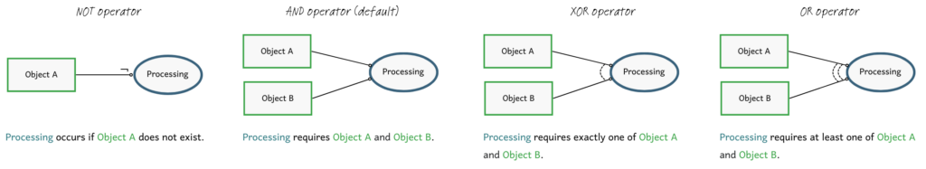
In OPM, there are four logical operators: NOT, AND, OR and XOR. These operators can be applied to procedural links to define the logical conditions required for each object to participate in a process. By default, objects are connected using the AND operator, meaning that all connected objects are necessary for the process to occur. The NOT operator is represented by a tilted “L”, the OR operator is shown with double dashed arches, and the XOR operator is depicted with a single dashed arch.
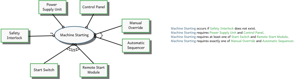
Let’s take the example of a machine startup process. If the safety interlock is present, the machine will not start — this is modelled using the NOT operator on the “Safety Interlock”. The startup process requires both the “Power Supply Unit” and the “Control Panel”, which are connected with the default AND operator since both are essential for the process. The machine can be started either remotely or physically, so the “Start Switch” and the “Remote Start Module” are linked using the OR operator. Finally, once the machine is running, it can either operate automatically or be manually overridden, both not both. This mutual exclusivity is captured by connecting the “Manual Override” and the “Automatic Sequencer” with the XOR operator.
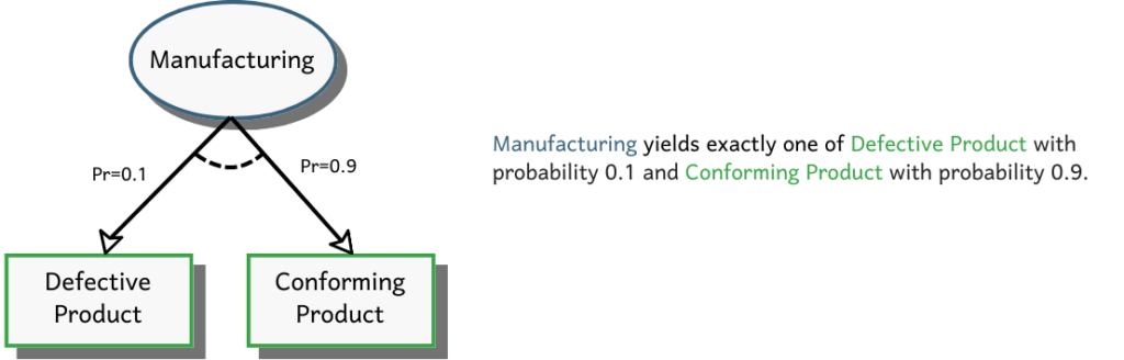
In scenarios where the XOR operator is used, probabilities can be assigned to each link, enabling the simulation of probabilistic outcomes. For example, consider a manufacturing process where there is a 0.1 chance of producing a defective product. This can be modelled by linking “Manufacturing” to both “Defective Product” and “Conforming Product” using result links with the XOR operator, and assigning probabilities to each outcome. When executed in OPCloud, the model will simulate the production process, generating results based on the specified probabilities.
Control Modifiers
In OPM, processes are typically understood to occur in the sequence implied by their spatial arrangement in the diagram. The process placed at the top is executed first, followed by subsequence processes below it. Processes arranged side by side are assumed to occur simultaneously, a concept known as the Timeline OPM Principle.
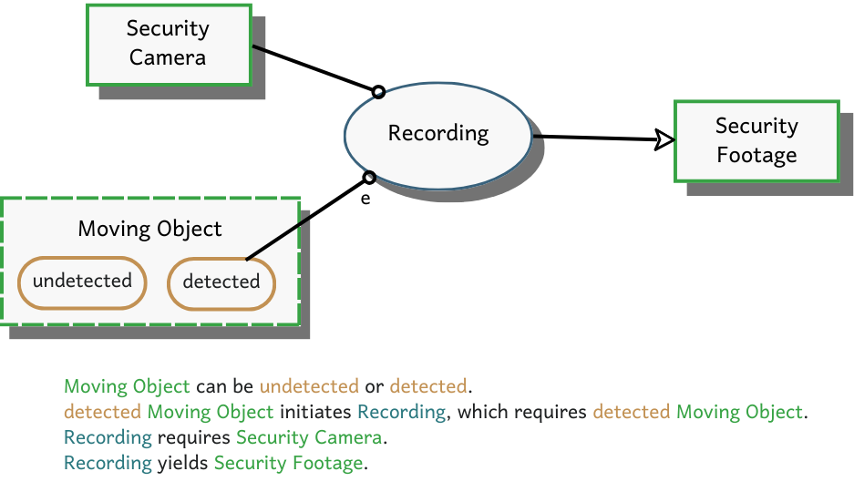
However, this default sequence can be altered using control modifiers, which allow for the modelling of conditions, iterations, and loops. OPM utilises the event-condition-action paradigm, which can be summarised as “on event, if condition, then action”. The event modifier signifies a trigger that initiates a process. For example, in a home security system, the camera starts recording when motion is detected. This can be modelled with an event link, connecting a “Moving Object” in the “detected” state to the “Recording” process.
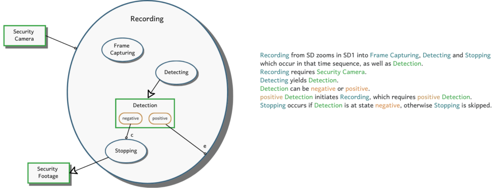
To further refine the “Recording” process, we can zoom into a lower level of abstraction, revealing subprocesses such as “Frame Capturing”, “Detecting”, and “Stopping” that occur in a specific sequence. The “Detecting” process results in a “Detection”, which can be either “negative” or “positive”. If nothing is detected, the “Stopping” process will proceed, represented by a procedural link with a condition modifier. If the detection remains positive, it re-triggers the “Recording” process, indicated by a procedural link with an event modifier.
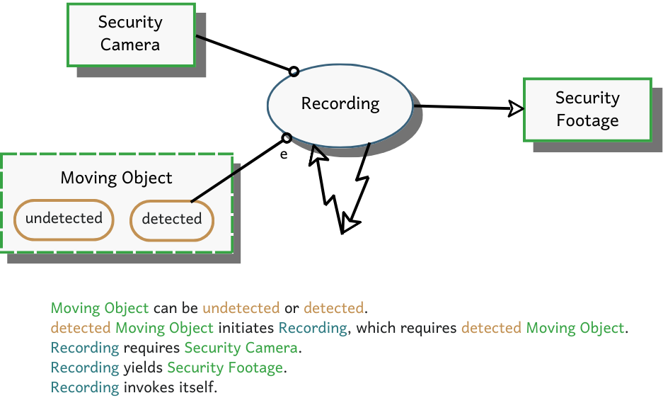
To signify that this process is iterative, we can add a self-invocation link at the higher abstraction level. This example illustrates how control modifiers can be used to adjust the inherent flow of OPM models, enabling the creation of more complex and meaningful scenarios.
Conclusions
Structure and behaviour are two fundamental aspects of any system, often referred to by other terms like form/function or structure/function. In this two-part series, we’ve explored how Object Process Methodology models both aspects using structural and procedural links.
To define what a process does, OPM uses procedural transforming links, which can represent creation, consumption, or effect. To specify who or what is responsible for or enabling a process, OPM employs procedural enabling links, including agent and instrument links. Logical operators are used to express more nuanced conditions, while control modifiers enable the modelling of complex flow of events.
OPM’s approach to linking these elements is designed to be both succinct and easy to grasp, while still offering the power to model complex systems comprehensively. What are your thoughts on the relationships in OPM? I’d love to hear your perspectives — feel free to share them in the comments below!
Leave a Reply